

Complete Electronics Hardware Design Course 2021
Complete Electronics Hardware Design Course 2021
MP4 | h264, 1280x720 | Lang: English | Audio: aac, 48000 Hz | 22h 56m | 17.2 GB
Complex Mixed Signal Board Design Course (Ethernet PHY, STM32F407, STM32F103, CH340C, DAC/MIC, 24Bit ADC, 36W Drivers)
What you'll learn
How to Extract Components information from Requirement Sheet
Selection of Component for Example: Ethernet PHY, Micro-Controller, Motor Driver, Mosfets, ADC, ADC/DAC, MIC etc.
How to Draw a Complex Schematic Block and Its Power Budget Diagrams
What are Differential pairs, USB2.0, I2Cs, UART/USART, CAN, MII/RMII, I2S and many more interfaces
EMI & EMC decisions for a Complex Mixed Signal Schematic Design
How to Create Design Rules Decision for Complex Mixed Signal Board
Layer Stack-Up Design (4L/6L/8L/12L) and Field Solver Simulation
How to Define Board shape and Rigid-Flex PCB Board
Components Placement planning for a Complex Board and its Execution
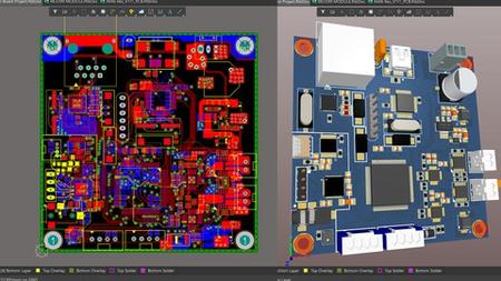
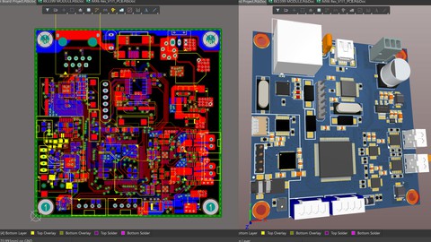
How to Layout a Complex Board with more than 10,000 interconnects, and Layout Optimization
Power Distribution Network (PDN Analysis) and How to read its Report + Resolve Issues
Requirements
For this course Student should have "Altium Designer" Installed on their PC / Laptop
Student Should have knowledge of Basic Electronics.
You do not need any prior knowledge of "Altium Designer" because we'll going to do everything from scratch.
Description
I have Divided this course into 4 Major Sections:
1st Section is Selection of Each Components whatever Going inside the Schematic.
2nd Section is Schematic Designing by Reading Datasheets.
3rd Stack-up 4L/6L/8L/12L, Components Placement Planning and Execution.
4th Inter Block and Intra Block Layout Planning and Execution.
Major Schematic Blocks that I have designed in this course are "Ethernet PHY 10/100 Mb/s", "I2S DAC for Headphone and Speaker", "MEMS MIC", "24BIT ADC", "36W Bi-Directional Brushed DC Motor Divers", "UART to USB TTL Converter", "STM32F103 Controller as Debugger and Programmer", "STM32F407 Main Controller", "Power Supply and Protections" and many more…. Various Subparts as you can see from the Curriculum.
You will also learn some Basic Blocks as well:
Pre-Schematic Design Blocks (Block Diagram and Power Budget)
Layer Stack-up Selection and Rules for Defining any Stack-up
Different Grounding Techniques( Signal Grounding, Earth Grounding, Chassis Grounding)
How to Create a RIGID-FLEX PCB and its Stack-up
How to do Pin-mapping using Cube-MX tool.
Power Distribution Network Analysis (PDN Analysis) of any PCB.
and many more things.
Ferrite Bead, ESD Diodes, and Magnetic Application and their selection.
How to do Placement and Layout Planning on Microsoft-Paint.
and many more….
After the completion of this course you can design any "Mixed Signal with Micro-Controller available across the world".
Major Controller used in this course are STM32F407XX, STM32F103XX apart from that we used PHY, and Some other sensors and ADC/ DAC as well.
Who this course is for:
People who have no experience with Hardware design and want to learn it
People Who want to Learn Complex Mixed Signal Board Design
People who want to learn PCB designing
People who want to Learn How to Select Components out of millions of chip available
People Who wan to Learn How Create a Board on Altium Designer.
People who want to enhance their Electronic Hardware Designing Skills.