
nTopology 5.23.2
nTopology 5.23.2 | 1.3 Gb
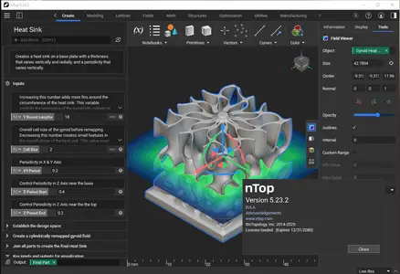
nTopology is pleased to announce the availability of nTopology 5.23.2. This major release features one of our most anticipated new nTop Fluids toolsets, bringing CFD into the iterative computational design loop. We also have new blocks to allow more nTop modeling.
nTop Fluids
- nTop Fluids is a new computational fluid dynamics (CFD) toolset integrated directly inside nTop. Eliminating the meshing and solving bottlenecks created by traditional tools, nTop Fluids brings CFD into the iterative computational design loop.-
- Workflows where you could use nTop Fluids:
. Internal flow for heat exchangers, manifolds, and valves
. Rapid iteration with GPU-solver and simplified meshing
. Creation of training datasets for machine learning
- You can access all the new toolset by enabling Beta and navigating to the new Fluids [Beta] ribbon.

![nTopology 5.23.2]()
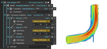
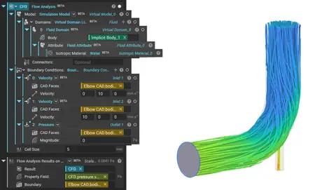
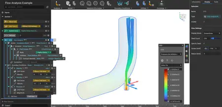
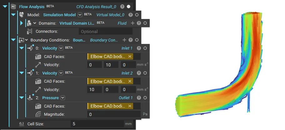
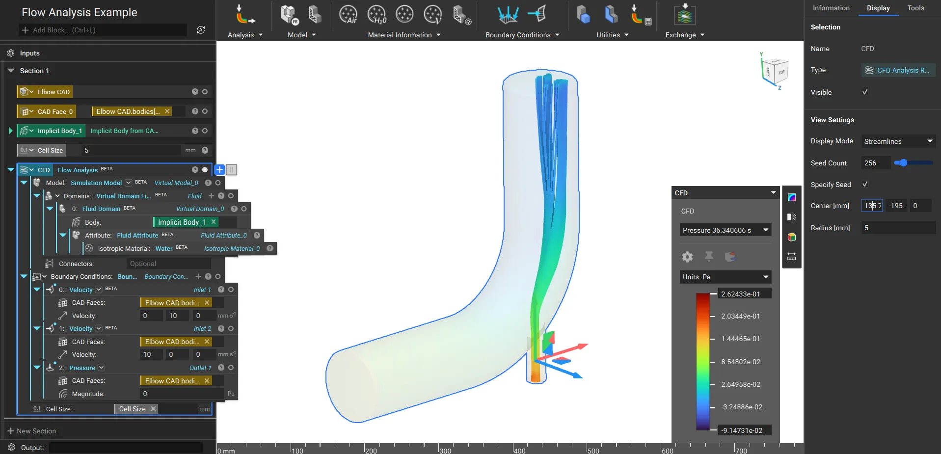
Flow Analysis
- Calculates the pressure and velocity on a Virtual Model. The solution uses the Lattice Boltzmann Method.
- A transient simulation is initiated and continues until the flow reaches a statistically steady state, returning time-averaged pressure and velocity fields.
Note: This block needs an NVIDIA GPU to run
- Location: Fluids [Beta] > Analysis
. Virtual Model: The Virtual Model represents the fluid domains to be simulated.
. Boundary Conditions: The Boundary Conditions to be used for the analysis. At least one Pressure and one Velocity Boundary condition are required.
. Cell Size: The size of the cells used in the analysis. Click on the Learn More link to find more information.
. Output: CFD Analysis Result
![nTopology 5.23.2]()
Fluid Attribute
- The Fluid Attribute block assigns the material properties as fluid attributes.
- Location: Fluids [Beta] > Material Information
. Isotropic Material: The underlying material
. Output: Fluid Attribute
Isotropic Fluid Property
- The Isotropic Fluid Property block defines an Isotropic Fluid Property.
- Location: Fluids [Beta] > Material Information
. Kinematic viscosity: The fluid's kinematic viscosity
. Output: Isotropic Fluid Property
Velocity
- The Velocity block is used to specify a fluid's velocity entering or leaving a domain. There is an overload in this block similar to other boundary conditions, to either use an Implicit Body or a CAD Face to select the boundary.
- Location: Fluids [Beta] > Boundary Conditions
. Boundary: The boundary selected for constant velocity.
. Velocity: Velocity Vector
. Output: Velocity
Air
- General Purpose Air at NIST (293.15 K, 100 KPa)
- Location: Fluids [Beta] > Material Information
. Output: Isotropic Material
Water
- General Purpose Water at NIST (293.15 K, 100 KPa)
- Location: Fluids [Beta] > Material Information
. Output: Isotropic Material
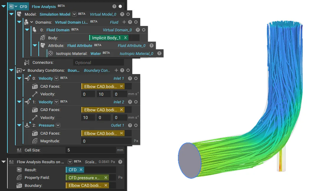
Flow Analysis Results on Boundary
- Calculates the average flow property (pressure or velocity) on the input Boundary of the Flow Analysis. Use the same boundary in Flow Analysis for the correct property results.
- Location: Fluids [Beta] > Utilities
. Result: The result from which to extract boundary values.
. Property Field: Property field from Flow Analysis.
. Boundary: Boundary to average Flow Analysis property on. The provided boundary must be the same as that used in the flow analysis.
. Output: Scalar
![nTopology 5.23.2]()
Modeling Blocks
- We are releasing new modeling blocks, allowing more nTop modeling and enabling an entire design space iteration.
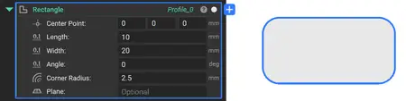
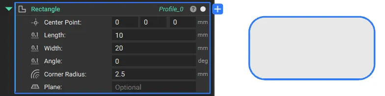
Rectangle
- The Rectangle block creates a rectangle profile from the input center point, length, and width.
- Location: Create > Primitives
. Center Point: Center point of the rectangle. If this does not lie on the Plane, it will be projected.
. Length: Length of the rectangle along the X-axis.
. Width: Width of the rectangle along the Y-axis.
. Angle: Angle of the rectangle with respect to the X-axis.
. Corner Radius: The circular radius to apply to the rectangle corners. The value will be queried from the Corner Radius field at the original Rectangle corners. If necessary, the value will be clamped to a valid range.
. Plane: Plane to define the orientation of the Rectangle. If no Plane is provided, the global XY plane will be used.
. Output: Profile
![nTopology 5.23.2]()
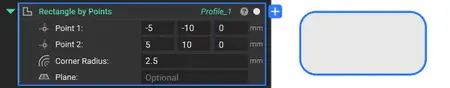
Rectangle by Points
- The Rectangle by Points block creates a rectangle profile from the two input corner points.
- Location: Create > Primitives
. Point 1: Minimum corner point of the rectangle. If this does not lie on the Plane, it will be projected.
. Point 2: Maximum corner point of the rectangle. If this does not lie on the Plane, it will be projected.
. Corner Radius: The circular radius will be applied to the rectangular corners. The value will be queried from the Corner Radius field at the original Rectangle corners. If necessary, the value will be clamped to a valid range.
. Plane: Plane to define the orientation of the Rectangle. If no Plane is provided, the global XY plane will be used.
. Output: Profile
![nTopology 5.23.2]()
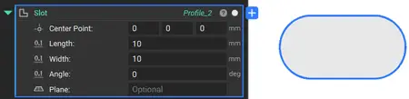
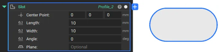
Slot
- The Slot block creates a slot profile from a center point, width, and height.
- Location: Create > Primitives
. Center Point: Center point of the slot. If this does not lie on the Plane, it will be projected.
. Length: Length of the slot along the X-axis. Defined by the center-to-center distance of the two arcs.
. Width: Width of the slot along the Y-axis.
. Angle: Angle of the slot with respect to the X-axis.
. Plane: Plane to define the orientation of the slot. If no Plane is provided, the global XY plane will be used.
. Output: Profile
![nTopology 5.23.2]()
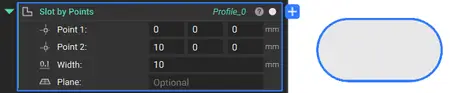
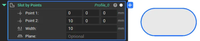
Slot by Points
- The Slot by Points block creates a slot profile from the two end points.
- Location: Create > Primitives
. Point 1: Point 1 of the slot. If this does not lie on the Plane, it will be projected.
. Point 2: Point 2 of the slot. If this does not lie on the Plane, it will be projected.
. Width: Width of the slot.
. Plane: Plane to define the orientation of the Rectangle. If no Plane is provided, the global XY plane will be used.
. Output: Profile
![nTopology 5.23.2]()
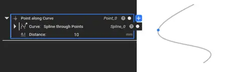
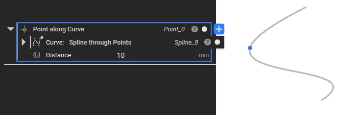
Point along Curve
- The Point along Curve block creates a point at a specified distance along a curve.
- Location: Create > Curves
. Curve: Curve along which to create a point.
. Distance: Distance along the curve to create the point. If this value is outside the range from zero to the length of the Curve, the point will be extrapolated. The extrapolation will be linear for Lines and Splines, and circular for Arcs. If Curve is a Polycurve, the extrapolation will be based on the type of segment at the corresponding endpoint.
. Output: Point
![nTopology 5.23.2]()
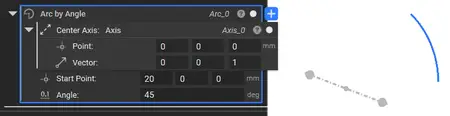
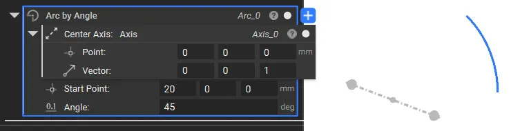
Arc by Angle
- The Arc by Angle block creates an arc based on the input Center Axis, Start Point, and Angle.
- Location: Create > Curves
. Center Axis: Axis that goes through the center point.
. Start Point: Start point of the arc.
. Angle: Angle of the arc. It will be clamped to be within -360 ° and +360 °.
. Output: Arc
![nTopology 5.23.2]()
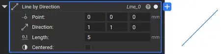
Line by Direction
- The Line by Direction block creates a line based on the input point, direction, and length.
- Location: Create > Curves
. Point: Start point of the line segment.
. Direction: Direction of the line segment. This vector will be normalized.
. Length: Length of the line segment.
. Centered: If checked, the line will be centered on the Point.
. Output: Line
![nTopology 5.23.2]()
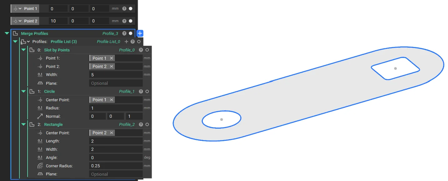
Merge Profiles
- The Merge Profile block combines multiple Profiles into a single Profile.
- Location: Create > Curves
. Profiles: Profiles to merge
. Output: Profile

![nTopology 5.23.2]()
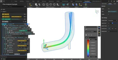
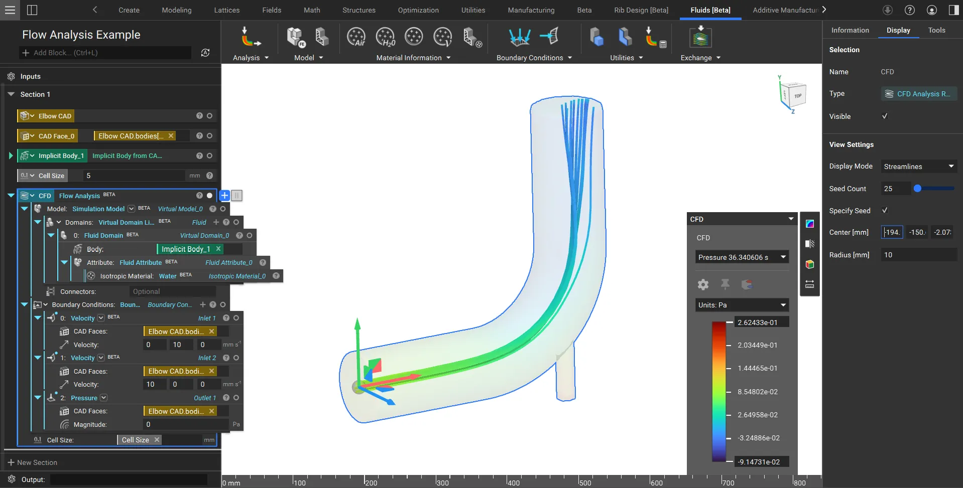
Usage Improvement
- We have introduced a new Streamlines visualization, which enables you to intuitively view the CFD results.
. View Settings is accessible in the Display tab of the Right Panel.
. Seed count controls the number of streamlines. Increase the seed count for denser streamlines.
. Specify Seed enables you to select a seeding region with the adjustable center point and radius.
![nTopology 5.23.2]()
![nTopology 5.23.2]()
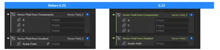
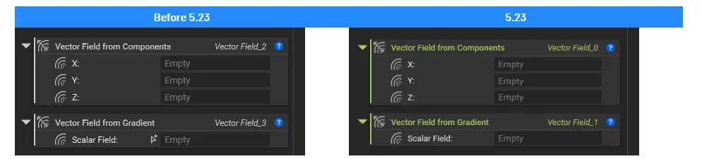
- We have updated the color of the blocks that output the Vector Field type to match that of the Scalar Field type.
![nTopology 5.23.2]()
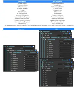
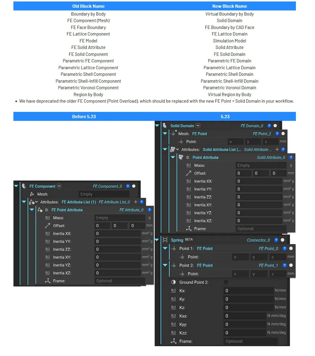
Block Updates
- We have updated our simulation blocks to be compatible with different solvers in nTop. We have also updated the older Simulation ribbon to be Structures to align with the new simulation capabilities of nTop. Many blocks have also been updated with name changes, input/output type changes, or both, but their behavior has not changed. This support article lists all the blocks and toolkit blocks that have been updated with more information regarding this update.
![nTopology 5.23.2]()
- We updated the Field Optimization block to fix an issue that caused the Min Infill thickness to differ when results converged.
- nTop Fluids is a new computational fluid dynamics (CFD) toolset integrated directly inside nTop. Eliminating the meshing and solving bottlenecks created by traditional tools, nTop Fluids brings CFD into the iterative computational design loop.-
- Workflows where you could use nTop Fluids:
. Internal flow for heat exchangers, manifolds, and valves
. Rapid iteration with GPU-solver and simplified meshing
. Creation of training datasets for machine learning
- You can access all the new toolset by enabling Beta and navigating to the new Fluids [Beta] ribbon.
nTopology 5.23.2

Flow Analysis
- Calculates the pressure and velocity on a Virtual Model. The solution uses the Lattice Boltzmann Method.
- A transient simulation is initiated and continues until the flow reaches a statistically steady state, returning time-averaged pressure and velocity fields.
Note: This block needs an NVIDIA GPU to run
- Location: Fluids [Beta] > Analysis
. Virtual Model: The Virtual Model represents the fluid domains to be simulated.
. Boundary Conditions: The Boundary Conditions to be used for the analysis. At least one Pressure and one Velocity Boundary condition are required.
. Cell Size: The size of the cells used in the analysis. Click on the Learn More link to find more information.
. Output: CFD Analysis Result
nTopology 5.23.2
Fluid Attribute
- The Fluid Attribute block assigns the material properties as fluid attributes.
- Location: Fluids [Beta] > Material Information
. Isotropic Material: The underlying material
. Output: Fluid Attribute
Isotropic Fluid Property
- The Isotropic Fluid Property block defines an Isotropic Fluid Property.
- Location: Fluids [Beta] > Material Information
. Kinematic viscosity: The fluid's kinematic viscosity
. Output: Isotropic Fluid Property
Velocity
- The Velocity block is used to specify a fluid's velocity entering or leaving a domain. There is an overload in this block similar to other boundary conditions, to either use an Implicit Body or a CAD Face to select the boundary.
- Location: Fluids [Beta] > Boundary Conditions
. Boundary: The boundary selected for constant velocity.
. Velocity: Velocity Vector
. Output: Velocity
Air
- General Purpose Air at NIST (293.15 K, 100 KPa)
- Location: Fluids [Beta] > Material Information
. Output: Isotropic Material
Water
- General Purpose Water at NIST (293.15 K, 100 KPa)
- Location: Fluids [Beta] > Material Information
. Output: Isotropic Material
Flow Analysis Results on Boundary
- Calculates the average flow property (pressure or velocity) on the input Boundary of the Flow Analysis. Use the same boundary in Flow Analysis for the correct property results.
- Location: Fluids [Beta] > Utilities
. Result: The result from which to extract boundary values.
. Property Field: Property field from Flow Analysis.
. Boundary: Boundary to average Flow Analysis property on. The provided boundary must be the same as that used in the flow analysis.
. Output: Scalar
nTopology 5.23.2
Modeling Blocks
- We are releasing new modeling blocks, allowing more nTop modeling and enabling an entire design space iteration.
Rectangle
- The Rectangle block creates a rectangle profile from the input center point, length, and width.
- Location: Create > Primitives
. Center Point: Center point of the rectangle. If this does not lie on the Plane, it will be projected.
. Length: Length of the rectangle along the X-axis.
. Width: Width of the rectangle along the Y-axis.
. Angle: Angle of the rectangle with respect to the X-axis.
. Corner Radius: The circular radius to apply to the rectangle corners. The value will be queried from the Corner Radius field at the original Rectangle corners. If necessary, the value will be clamped to a valid range.
. Plane: Plane to define the orientation of the Rectangle. If no Plane is provided, the global XY plane will be used.
. Output: Profile
nTopology 5.23.2
Rectangle by Points
- The Rectangle by Points block creates a rectangle profile from the two input corner points.
- Location: Create > Primitives
. Point 1: Minimum corner point of the rectangle. If this does not lie on the Plane, it will be projected.
. Point 2: Maximum corner point of the rectangle. If this does not lie on the Plane, it will be projected.
. Corner Radius: The circular radius will be applied to the rectangular corners. The value will be queried from the Corner Radius field at the original Rectangle corners. If necessary, the value will be clamped to a valid range.
. Plane: Plane to define the orientation of the Rectangle. If no Plane is provided, the global XY plane will be used.
. Output: Profile
nTopology 5.23.2

Slot
- The Slot block creates a slot profile from a center point, width, and height.
- Location: Create > Primitives
. Center Point: Center point of the slot. If this does not lie on the Plane, it will be projected.
. Length: Length of the slot along the X-axis. Defined by the center-to-center distance of the two arcs.
. Width: Width of the slot along the Y-axis.
. Angle: Angle of the slot with respect to the X-axis.
. Plane: Plane to define the orientation of the slot. If no Plane is provided, the global XY plane will be used.
. Output: Profile
nTopology 5.23.2
Slot by Points
- The Slot by Points block creates a slot profile from the two end points.
- Location: Create > Primitives
. Point 1: Point 1 of the slot. If this does not lie on the Plane, it will be projected.
. Point 2: Point 2 of the slot. If this does not lie on the Plane, it will be projected.
. Width: Width of the slot.
. Plane: Plane to define the orientation of the Rectangle. If no Plane is provided, the global XY plane will be used.
. Output: Profile
nTopology 5.23.2
Point along Curve
- The Point along Curve block creates a point at a specified distance along a curve.
- Location: Create > Curves
. Curve: Curve along which to create a point.
. Distance: Distance along the curve to create the point. If this value is outside the range from zero to the length of the Curve, the point will be extrapolated. The extrapolation will be linear for Lines and Splines, and circular for Arcs. If Curve is a Polycurve, the extrapolation will be based on the type of segment at the corresponding endpoint.
. Output: Point
nTopology 5.23.2
Arc by Angle
- The Arc by Angle block creates an arc based on the input Center Axis, Start Point, and Angle.
- Location: Create > Curves
. Center Axis: Axis that goes through the center point.
. Start Point: Start point of the arc.
. Angle: Angle of the arc. It will be clamped to be within -360 ° and +360 °.
. Output: Arc
nTopology 5.23.2
Line by Direction
- The Line by Direction block creates a line based on the input point, direction, and length.
- Location: Create > Curves
. Point: Start point of the line segment.
. Direction: Direction of the line segment. This vector will be normalized.
. Length: Length of the line segment.
. Centered: If checked, the line will be centered on the Point.
. Output: Line
nTopology 5.23.2

Merge Profiles
- The Merge Profile block combines multiple Profiles into a single Profile.
- Location: Create > Curves
. Profiles: Profiles to merge
. Output: Profile
nTopology 5.23.2
Usage Improvement
- We have introduced a new Streamlines visualization, which enables you to intuitively view the CFD results.
. View Settings is accessible in the Display tab of the Right Panel.
. Seed count controls the number of streamlines. Increase the seed count for denser streamlines.
. Specify Seed enables you to select a seeding region with the adjustable center point and radius.
nTopology 5.23.2
nTopology 5.23.2
- We have updated the color of the blocks that output the Vector Field type to match that of the Scalar Field type.
nTopology 5.23.2
Block Updates
- We have updated our simulation blocks to be compatible with different solvers in nTop. We have also updated the older Simulation ribbon to be Structures to align with the new simulation capabilities of nTop. Many blocks have also been updated with name changes, input/output type changes, or both, but their behavior has not changed. This support article lists all the blocks and toolkit blocks that have been updated with more information regarding this update.
nTopology 5.23.2
- We updated the Field Optimization block to fix an issue that caused the Min Infill thickness to differ when results converged.
nTopology 5.23.2

nTopology introduced the concept of implicit modeling for mechanical design, which is an innovative, modern, and scalable way define parts and products. It has many benefits to end-users and companies, such as the elimination of model failures, speed of changes or iterations, and scalability to name a few. But implicit modeling enables so much more. In this informational session, we'll explore a topic that is redefining product development – field-driven design. In short, field-driven design is a way for design, analysis, and manufacturing teams to overlay information into one engineering model. This approach enables orders of magnitude increase in design iteration speed and greatly improves collaboration between teams.
How Field-Driven Design Allows Engineers to Design for Additive Manufacturing
Watch this information session where we'll define field-driven design, show examples of how it enables better knowledge sharing, and show how it promotes the development of more sophisticated, highly engineered products. You'll also better understand how nTopology is addressing today's engineering problems through its nTop Platform product.
nTopology was founded in 2015 to enable engineers and designers to create any geometry — no matter how complex — and meet the requirements of high-performance products.
Owner: nTopology
Product Name: nTopology
Version: 5.23.2
Supported Architectures: x64
Website Home Page : www.ntop.com
Languages Supported: english
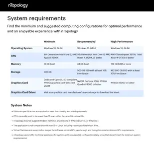
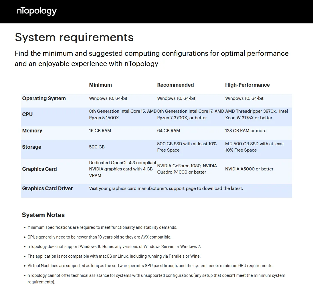
System Requirements: Windows *
Size: 1.3 Gb
nTopology 5.23.2
Please visit my blog
Added by 3% of the overall size of the archive of information for the restoration
No mirrors please

![nTopology 5.23.2]()
Added by 3% of the overall size of the archive of information for the restoration
No mirrors please
nTopology 5.23.2