


Siemens Solid Edge Electrical Design 2021
Siemens Solid Edge Electrical Design 2021 | 1.8 Gb
Languages: 中文 (Simplified), 中文 (Traditional), Čeština, English, Français, Deutsch,
Magyar, Italiano, 日本語, 한국어, Polski, Português-Brazilian, Русский, Español
Languages: 中文 (Simplified), 中文 (Traditional), Čeština, English, Français, Deutsch,
Magyar, Italiano, 日本語, 한국어, Polski, Português-Brazilian, Русский, Español
Siemens Digital Industries Software announces the 2021 version of Solid Edge Wiring and Harness Design software. These mod-ules enable engineers to collaborate seamlessly between electrical and 3D mechanical design.
Bellow summarizes new features and enhancements across the Solid Edge Wiring and Harness Design flow organized under the following functional areas:
- General Features
- Electrical Distribution
- Harness Engineering
- Data Management & Integrations
Layout Design
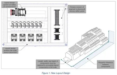
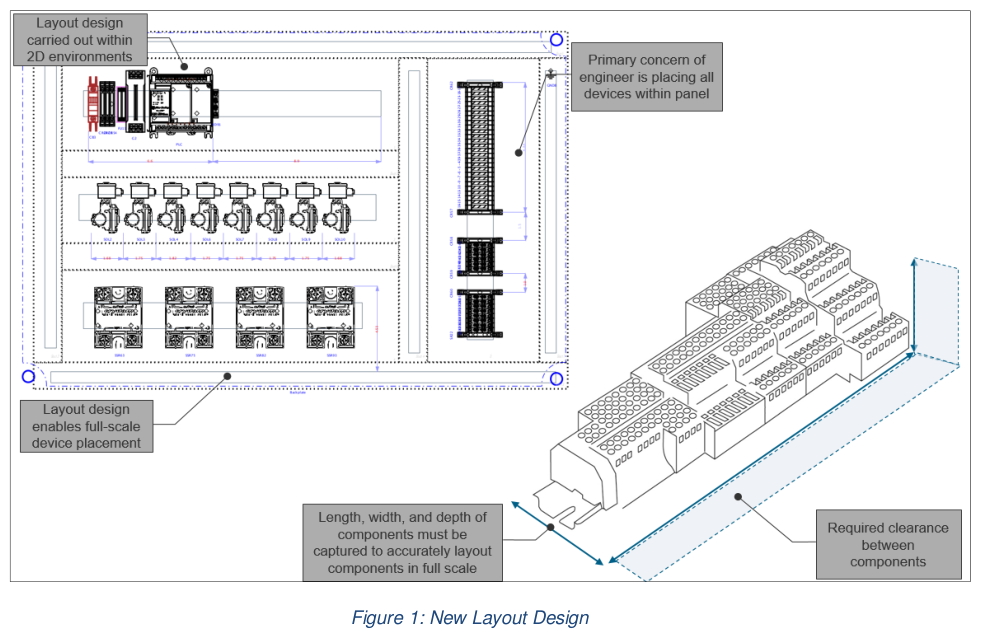
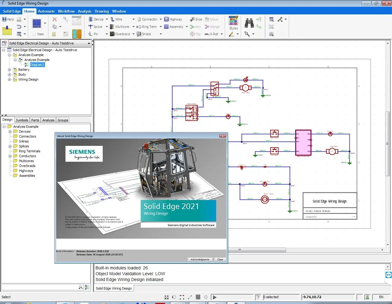
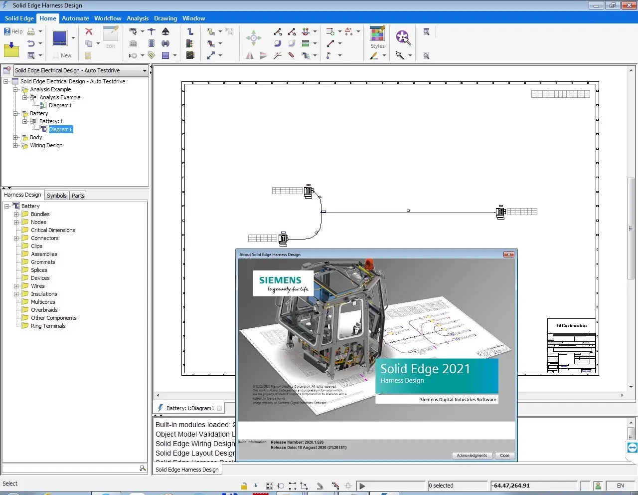
Solid Edge Wiring and Harness Design’s new layout design type associates the electrical requirements to a physical context for defining 2D layouts (Figure 1).
![Siemens Solid Edge Electrical Design 2021]()
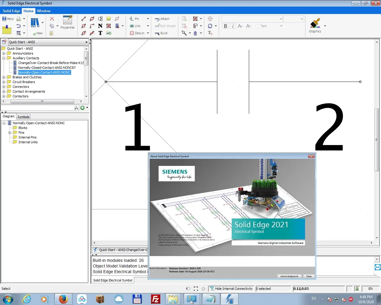
Streamlined Symbol Exchange
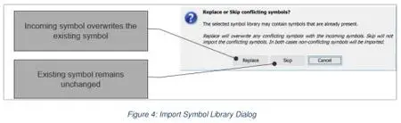
In Solid Edge Electrical Symbol, symbol libraries containing conflicting symbols with existing libraries can be imported. The option to replace existing symbols or skip the import in the event of a conflict (Figure 4) can be selected at the beginning of the import process to allow the import to run uninterrupted.
![Siemens Solid Edge Electrical Design 2021]()
Custom Tables
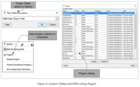
The ability to add custom tables has been added via plugins (Figure 5).
![Siemens Solid Edge Electrical Design 2021]()
Streamlined Graphical Rendering and Manipulation
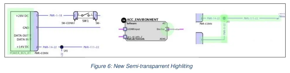
On busy diagrams, locating and resizing objects can be difficult. A number of graphical enhancements now make this process easier. A glowing, semi-transparent highlight will make objects more noticeable when selected directly (Figure 6).

![Siemens Solid Edge Electrical Design 2021]()
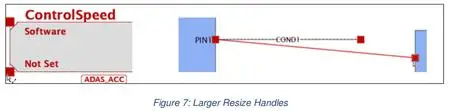
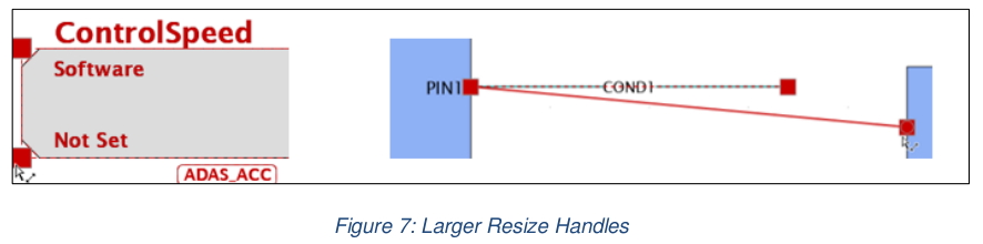
Resizing handles are now more prominent and offer a bigger clicking area that adapts to different zoom levels, making them easier to find and grab (Figure 7).
![Siemens Solid Edge Electrical Design 2021]()
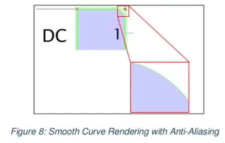
The graphics engine has also been upgraded to render curves more smoothly for higher quality diagram display (Figure 8).
![Siemens Solid Edge Electrical Design 2021]()
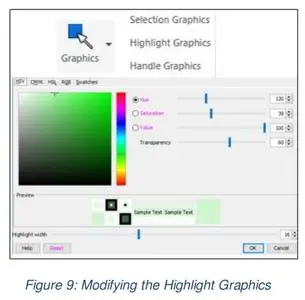
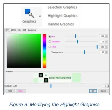
The selection, highlight, and handle graphics can be modified via the Graphics pulldown under the Window tab (Figure 9).
![Siemens Solid Edge Electrical Design 2021]()
Solid Edge Wiring and Harness Design’s new layout design type associates the electrical requirements to a physical context for defining 2D layouts (Figure 1).
Siemens Solid Edge Electrical Design 2021
Streamlined Symbol Exchange
In Solid Edge Electrical Symbol, symbol libraries containing conflicting symbols with existing libraries can be imported. The option to replace existing symbols or skip the import in the event of a conflict (Figure 4) can be selected at the beginning of the import process to allow the import to run uninterrupted.
Siemens Solid Edge Electrical Design 2021

Custom Tables
The ability to add custom tables has been added via plugins (Figure 5).
Siemens Solid Edge Electrical Design 2021

Streamlined Graphical Rendering and Manipulation
On busy diagrams, locating and resizing objects can be difficult. A number of graphical enhancements now make this process easier. A glowing, semi-transparent highlight will make objects more noticeable when selected directly (Figure 6).
Siemens Solid Edge Electrical Design 2021
Resizing handles are now more prominent and offer a bigger clicking area that adapts to different zoom levels, making them easier to find and grab (Figure 7).
Siemens Solid Edge Electrical Design 2021
The graphics engine has also been upgraded to render curves more smoothly for higher quality diagram display (Figure 8).
Siemens Solid Edge Electrical Design 2021

The selection, highlight, and handle graphics can be modified via the Graphics pulldown under the Window tab (Figure 9).
Siemens Solid Edge Electrical Design 2021
This file (Solid_Edge_Wiring_And_Harness_Design_Release_Highlights_v2021.pdf) lists all the new and updated features and also bug fixes that are available in Solid Edge Wiring and Harness Design 2021.
Siemens Solid Edge Electrical Design 2021


Siemens Solid Edge Electrical Design 2021
Siemens Solid Edge Electrical Design 2021
Siemens Solid Edge Electrical Design 2021

Siemens Solid Edge Electrical Design 2021
Solid Edge Electrical Design utilizes electrical circuit diagrams from popular eCAD systems to automate the creation of routed wiring and cable harnesses. Electrical and mechanical design teams can now collaborate more closely and create a complete digital mockup that includes cables and wires. Dedicated tools deliver streamlined ways to create wires, cables and bundles.
Two Solid Edge software modules do just that: Solid Edge Wiring Design and Solid Edge Harness Design. These mod-ules enable engineers to collaborate seamlessly between electrical and 3D mechanical design.
The Solid Edge electrical design modules are available individually or as a bundled solution.
Based on technology from Mentor, a Siemens business, Solid Edge Wiring Design and Solid Edge Harness Design enable engineers to create electrical systems and collaborate directly with the mechanical design to optimize the overall product design. Engineers can accommodate space reservation, clash detection and hazard avoidance in the mechanical domain, too.
Solid Edge Wiring Design - Designing the wiring of electrical sys-tems is made easy with an electrically-aware schematic tool. Solid Edge Wiring Design comes with built-in verification and design rule checks to confirm correct-by-construction design, and an intelligent parts library to accel-erate the design process with automatic part selection. The connected mode available in Solid Edge Electrical Routing allows dynamic computer-aided design (CAD)/mechanical computer-aided design (MCAD) collaboration with cross probing and dynamic updating between mechanical and electrical domains.
Solid Edge Harness Design - Solid Edge Harness Design is a design application for in-house production or build-to-print purposes. You can design harnesses in a standalone mode, or they can be derived from the schematic in Solid Edge Wiring Design. Solid Edge Harness Design is fully integrated with Solid Edge 3D design tools, providing a real-world 3D experience that facilitates electronic computer-aided design (ECAD)/MCAD collaboration. Connector face views and tables make it easy for designers to determine how wires terminate, and the intelligent parts library drives the automatic selection of terminals, seals and wires.
Symbols and parts - Solid Edge Wiring Design and Solid Edge Harness Design contain robust part and model repositories, which support the automation of parts selec-tion and the automatic selection of terminal plugs and seals for each con-nector. The International Electrotechnical Commission (IEC) and American National Standards Institute (ANSI) symbol and parts libraries are also supported
Solid Edge Wiring and Harness Design combined with the Solid Edge mechani-cal design environment enables companies to bring products to market faster without sacrificing quality.
Wiring and Harness Design in Solid Edge
Siemens Digital Industries (DI) is an innovation leader in automation and digitalization. Closely collaborating with partners and customers, DI drives the digital transformation in the process and discrete industries. With its Digital Enterprise portfolio, DI provides companies of all sizes with an end-to-end set of products, solutions and services to integrate and digitalize the entire value chain. Optimized for the specific needs of each industry, DI’s unique portfolio supports customers to achieve greater productivity and flexibility. DI is constantly adding innovations to its portfolio to integrate cutting-edge future technologies. Siemens Digital Industries has its global headquarters in Nuremberg, Germany, and has around 75,000 employees internationally.
Siemens PLM Software is a world-leading provider of product lifecycle management and manufacturing operations management software. We help thousands of companies realize innovation by optimizing their processes, from planning and development through manufacturing, production and support.
Product: Siemens Solid Edge Electrical Design
Version: 2021
Supported Architectures: x64
Website Home Page : https://solidedge.siemens.com/
Language: multilanguage
System Requirements: PC *
Size: 1.8 Gb
Supported Operating Systems
Solid Edge Wiring and Harness Design clients are supported in the following environments:
- Windows 10 Enterprise or Professional (64-bit only) version 1709 or later (recommended)
- Windows 8.1 Pro or Enterprise (64-bit only)
Solid Edge Wiring and Harness Design servers are supported in the following environments:
- Windows Server 2019 (recommended)
- Windows Server 2016
- Windows Server 2012 R2
Support for maintenance releases (service packs) on these operating systems versions will cease when the manufacturers end general support for them.
Memory (RAM) and Disk Space Requirements
The minimum memory required by Solid Edge Wiring and Harness Design is 4GB. The recommended memory is 8GB or more. Recommended available disk space for the client is 10GB, and 25GB for the server. In standalone configurations where the client and server are on the same machine, these values should be combined. It is recommended to install the embedded database on fast physical storage such as an SSD (solid state drive) array. It is recommended to use striped RAID for the database.
Display Resolution
The client applications require a minimum video resolution of 1024x768 16-bit color, or higher. Recommended video resolution is 1920x1080 or higher. 24-bit color displays are recommended for client machines.
Machine and CPU Requirements
A modern physical or virtual machine with underlying hardware no older than 4 years is recommended with a professional grade CPU having at least two cores. The recommendation intentionally encompasses a wide variety of makes, models, generations, cache sizes, frequencies, memory types and so on due to rapid evolution of hardware available on the market.
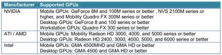
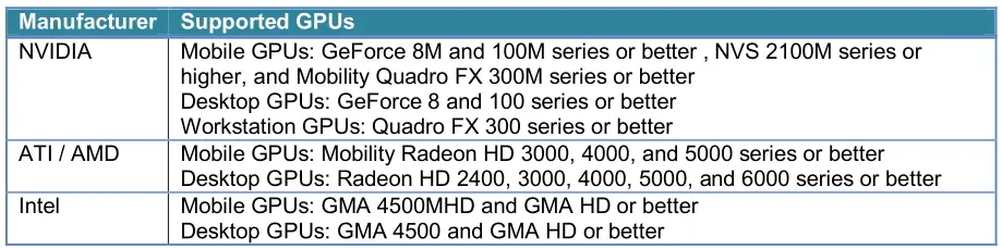
Graphics Processing Unit Requirements
The following graphics processing units (GPU) are required for 3D operations and recommended for 2D operations on both physical and virtual machines.
![Siemens Solid Edge Electrical Design 2021]()
Solid Edge Wiring and Harness Design clients are supported in the following environments:
- Windows 10 Enterprise or Professional (64-bit only) version 1709 or later (recommended)
- Windows 8.1 Pro or Enterprise (64-bit only)
Solid Edge Wiring and Harness Design servers are supported in the following environments:
- Windows Server 2019 (recommended)
- Windows Server 2016
- Windows Server 2012 R2
Support for maintenance releases (service packs) on these operating systems versions will cease when the manufacturers end general support for them.
Memory (RAM) and Disk Space Requirements
The minimum memory required by Solid Edge Wiring and Harness Design is 4GB. The recommended memory is 8GB or more. Recommended available disk space for the client is 10GB, and 25GB for the server. In standalone configurations where the client and server are on the same machine, these values should be combined. It is recommended to install the embedded database on fast physical storage such as an SSD (solid state drive) array. It is recommended to use striped RAID for the database.
Display Resolution
The client applications require a minimum video resolution of 1024x768 16-bit color, or higher. Recommended video resolution is 1920x1080 or higher. 24-bit color displays are recommended for client machines.
Machine and CPU Requirements
A modern physical or virtual machine with underlying hardware no older than 4 years is recommended with a professional grade CPU having at least two cores. The recommendation intentionally encompasses a wide variety of makes, models, generations, cache sizes, frequencies, memory types and so on due to rapid evolution of hardware available on the market.
Graphics Processing Unit Requirements
The following graphics processing units (GPU) are required for 3D operations and recommended for 2D operations on both physical and virtual machines.
Siemens Solid Edge Electrical Design 2021
Please visit my blog
Added by 3% of the overall size of the archive of information for the restoration
No mirrors please

![Siemens Solid Edge Electrical Design 2021]()
Added by 3% of the overall size of the archive of information for the restoration
No mirrors please
Siemens Solid Edge Electrical Design 2021