

Siemens Simcenter FEMAP 2021.1 MP2

Siemens Simcenter FEMAP 2021.1 MP2 | 2.4 Gb
Languages: 中文 (Simplified), 中文 (Traditional), English, Deutsch, 日本語
Languages: 中文 (Simplified), 中文 (Traditional), English, Deutsch, 日本語
The Siemens Digital Industries Software development team is pleased to announce the availability of Simcenter Femap 2021.1 MP2. This release provides a variety of improvements that will help your productivity across the simulation workflow.
FEMAP 2021.1 New Features and Corrections
Connection Properties, Regions, and Connectors
- Corrected an issue where regions which had no entities defined in them before using the Delete, Model, Mesh command were being deleted even though nothing had been deleted from the region by the command. Moving forward, the command still deletes regions that become empty after the Delete, Model, Mesh command is used, but regions that are already empty are not deleted (PR# 9984501)
Geometry
- Corrected issue with several commands where the color and layer of new geometry was being inherited from the original geometry instead of being created using the Active Color and on the Active Layer.
Graphics
- Corrected an issue where renumbering Solids caused incorrect graphics behavior including failure to be able to highlight a solid from the Model Info Tree. The workaround is to use the “File, Rebuild” command and choose “Yes” in the dialog box which performs a full database rebuild after renumbering solids.
User Interface - General
- Corrected an issue in Geometry Parameters dialog box that prevented Palette buttons from working correctly and limited the range of IDs available for “Next Surface” and “Next Volume”.
- Corrected issue where the “Coordinate”, “Around Point”, “Around Vector”, and “Around Plane” options on the Pick^ menu of the standard entity selection dialog box where not working when the “New Picking” option was enabled on the “Graphics” tab of the Preferences dialog box. This issue also impacted API calls which mimic the functionality of those options on the Pick^ menu (for instance, the AddCoordinate method on the Set Object). The workaround was to disable the “New Picking” option using the File, Preferences command. (PR# 9992875 and PR# 9992900)
- Corrected issue which allowed entities to be selected multiple times when multiple views existed and the “New Picking” option was enabled on the “Graphics” tab of the Preferences dialog box. The workaround was to disable the “New Picking” option using the File, Preferences command.
- Corrected issue where certain weld elements could not be selected when the “New Picking” option was enabled on the “Graphics” tab of the Preferences dialog box. The workaround was to disable the “New Picking” option using the File, Preferences command.
- Corrected issue where RBE2 and RBE3 Rigid elements could not be selected when the “New Picking” option was enabled on the “Graphics” tab of the Preferences dialog box. The workaround was to disable the “New Picking” option using the File, Preferences command (PR# 9994290).
- Corrected issue where RSPLINE Rigid elements could not be selected when the “New Picking” option was enabled on the “Graphics” tab of the Preferences dialog box. The workaround was to disable the “New Picking” option using the File, Preferences command (PR# 9994554). User Interface - Dockable Panes
Meshing Toolbox - Overall
- Corrected issue that could cause drop-down buttons to get drawn underneath the scrollbar (PR# 9976919).
PostProcessing Toolbox - Overall
- Corrected issue that could cause drop-down buttons to get drawn underneath the scrollbar (PR# 9976919).
Entity Editor
- Corrected issue that could cause drop-down buttons to get drawn underneath the scrollbar (PR# 9976919).
Data Table
- Corrected an issue which could cause and Improper Argument error to be issued when the number of columns in the Data Table become very large.
Interfaces - Nastran
- Corrected issue which prevented PELAS entries from being written to Nastran input file when “Portion of Model to Write” option in NASTRAN Bulk Data Options dialog box of the Analysis Set Manager was pointing to a Group which contained DOF Spring properties and elements.
Interfaces - ABAQUS
- Corrected issue where ABAQUS explicit runs would not direct results to ODB file with default Analysis Manager Settings. Default settings changed from “3..Print and PostProcess” to “8..Print and Output Database”.
Interfaces - LS-DYNA
- Corrected an issue where a stand-alone Connection Regions (i.e., Connection Regions which are not used by any Connectors) where not written to LS-DYNA input file (PR# 9984501).
Element - Weld/Fastener
- Corrected issue when deleting weld elements which have Weld Type set to “1..Elem to Elem Vertex (ELEMID)” which could lead node counters to become incorrect, thus allowing nodes which are still referenced by other elements to be deleted inadvertently.
Meshing
- Corrected an issue with the Mesh, Remesh, Update command. Previously if the “Fast Tri Mesh” option was enabled, the resulting elements were created with normal directions that were opposite the original elements.
Model Update
- Corrected issue when using the Modify, Move By, Coord Sys; Modify, Rotate By, Coord Sys; Modify, Reflect Coord Sys; or Modify, Align, Coord Sys command which caused the selected coordinate systems to remain unchanged when the “Coordinate Systems” option was disabled in the “Other Entities to Include” section. Now, as expected, only the selected coordinate systems will be updated and coordinate systems that reference the selected ones will remain unchanged. In addition, if the “Geometry and Mesh” option is enabled in the “Other Entities to Include” section, but “Coordinate Systems” is disabled, only the geometry and mesh which directly reference a selected coordinate system will be updated, not any geometry or mesh which is defined in a coordinate system which references a selected coordinate system.
Output and Post-Processing
- Corrected an issue which prevented complex element stresses/strains to be read in at all for axisymmetric quad elements (CQUADX4/CQUADX8) when used in a frequency response analysis performed with Simcenter Nastran.
Tools
- Corrected an issue in the Tools, Check, Mesh Interference command when Plot Only elements were included in the selection of elements to check mesh interference. Plot Only elements have zero thickness, however they were being treated as infinitely thin volumes causing numerous false indications of mesh interference. Moving forward, the zero thickness of Plot Only elements has been removed from the algorithm and the mesh interference check now works as expected.
API
- Corrected issues in User Defined Graphics Object where Methods used to locate graphics based on existing Femap entities did not work as expected. The methods include:
CollectorAddPointEntityLocations, CollectorAddPointEntityFaceLocations,
CollectorAddSymbolEntityLocations, CollectorAddSymbolEntityFaceLocations,
CollectorAddSymbolEntityFaceNormalLocations,
CollectorAddSymbolEntityFaceNormalAutoLocations, CollectorAddSymbolEntityEdgeLocations,
CollectorAddSymbolEntityEdgeAutoLocations, CollectorAddSymbolREAL8EntityLocations,
CollectorAddSymbolREAL8EntityFaceLocations,
CollectorAddSymbolREAL8EntityFaceNormalLocations,
CollectorAddSymbolREAL8EntityFaceNormalAutoLocations,
CollectorAddSymbolREAL8EntityEdgeLocations,
CollectorAddSymbolREAL8EntityEdgeAutoLocations, CollectorAddTextEntityLocations,
CollectorAddTextEntityFaceLocations, CollectorAddTextINT4EntityLocations,
CollectorAddTextINT4EntityFaceLocations, CollectorAddTextREAL8EntityLocations, and
CollectorAddTextREAL8EntityFaceLocations
Siemens Simcenter FEMAP 2021.1 MP2

Simcenter Femap software is a standalone finite element modeling (FEM) pre- and postprocessor for engineering simulation and analysis. The software is computer-aided design (CAD) independent and can import geometry from all major CAD platforms. It supports most CAD data formats. Simcenter Femap also works in combination with a wide variety of FEA solvers, including Simcenter Nastran® software.
Simcenter Femap, which is part of the Xcelerator portfolio, the comprehensive and integrated portfolio of software and services from Siemens Digital Industries Software, is now being released on a biannual schedule in the spring and the fall, which began with version 2019.1 and continues with version 2021.1. The software is now referred to as Simcenter Femap to reflect that it is a part of the Simcenter portfolio of Siemens computer-aided engineering (CAE) products. For the same reason, NX Nastran software is now Simcenter Nastran software.
The latest release provides a variety of enhancements that will improve your productivity across the simulation workflow. A large amount of functionality added to 2021.1 focuses on facilitating mesh creation and modification. First, matching mesh sizes and determining mesh propagation between disconnected geometric entities can be specified based on the proximity of edge curves to one another. To determine where these mesh propagation options will be enforced, tools were created in the new mesh control explorer pane to provide visual feedback for edge curves, which are fully paired, partially paired or unpaired, along with other tools to visualize which surfaces are paired for solid meshing or have a surface mesh approach assigned. In addition, multiple tools in the meshing toolbox can be used to update an existing hex mesh. Another area of expanded capabilities is support for MSC Nastran SOL 400. From a modeling standpoint, items have been added to specify property extensions, nonlinear materials and contact options designed for use with SOL 400. At the same time, a new analysis type may be selected that offers user interface (UI) elements to define critical and useful solver parameters for SOL 400. Finally, updates have also been implemented for Simcenter Nastran and Abaqus.
What's New in Simcenter Femap 2021.1 – Mesh Control Explorer
Short video showcasing new capabilities in Simcenter Femap 2021.1 around meshing, specifically the Mesh Control Explorer
What's New in Simcenter Femap 2021.1 – Analysis Filtering
Short video showcasing new capabilities in Simcenter Femap 2021.1 around solver support, specifically Analysis Filtering
What's New in Simcenter Femap 2021.1– Hex Mesh Updating
Short video showcasing new capabilities in Simcenter Femap 2021.1 around meshing, specifically hex mesh updating.
Siemens PLM Software. a business unit of the Siemens Digital Factory Division, is a leading global provider of software solutions to drive the digital transformation of industry, creating new opportunities for manufacturers to realize innovation. With headquarters in Plano, Texas, and over 140,000 customers worldwide, Siemens PLM Software works with companies of all sizes to transform the way ideas come to life, the way products are realized, and the way products and assets in operation are used and understood.
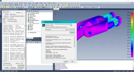
Product: Siemens Simcenter FEMAP
Version: 2021.1 MP2 with NX Nastran
Supported Architectures: x64
Website Home Page : www.plm.automation.siemens.com
Language: 中文 (Simplified), 中文 (Traditional), English, Deutsch, 日本語
System Requirements: PC *
Size: 2.4 Gb
Welcome to FEMAP! This document will help you to setup your computer so that you can immediately begin to explore the many capabilities of FEMAP.
This document contains information specific to getting started on a PC, which includes 64-bit versions for Windows 7, Win-dows 8, Windows 8.1, and Windows 10.
The FEMAP installer contains only the 64-bit version of FEMAP, as a 32-bit version is no longer available.
Hardware/Software Requirements
There are no special hardware/software requirements for FEMAP beyond those imposed by the Windows operating systems. There are many types of hardware that will allow you to use FEMAP. Proper choice of hardware, however, can often make the difference between frustration and productivity. Here are a few suggestions:
- Memory, RAM
- Memory, (Hard Disk)
- Graphics Boards
-Abaqus ODB Requirements
Memory, RAM
You will need at least 128 Mbytes of RAM to run FEMAP and the Parasolid solid modeling engine, which is the default. Obviously, the more amount of RAM the better. Adding RAM can be one of the most cost effective means of increasing per-formance.If using the “Standard” geometry Engine in FEMAP, you can actually run with as little as 32 Mbytes of RAM. This is not a recommended configuration.
Memory, (Hard Disk)
Required hard disk space is very difficult to estimate, but in general you will never have enough. Analysis results will be the main driver of any disk space requirement. Models are typically relatively small. A model with 1000 nodes and 1000 ele-ments would typically be less than 1 Mbyte in size. Output from an analysis of that model, however, could be 5 Mbytes, 10 Mbytes or even larger, depending on the output you request. To estimate total disk space, you need to first estimate how many models you will have on-line simultaneously, the approximate size of those models, and the type of output you will request. It is recommend to have as much disk space as budget will allow, as each version of FEMAP can support larger and larger models, which in turn create larger and larger amounts of output.
Graphics Boards
While, standard graphics adapters may work very well with FEMAP, having a specialized board with support for OpenGL will provide increased graphical performance when dynamically rotating large, complex models. They also usually provide higher resolution and more colors, which make graphics easier to see and more realistic. Also, in order to use the “Perfor-mance Graphics” option, a graphics card which supports OpenGL 4.2 is required.
Please visit my blog
Added by 3% of the overall size of the archive of information for the restoration
No mirrors please

![Siemens Simcenter FEMAP 2021.1 MP2]()
Added by 3% of the overall size of the archive of information for the restoration
No mirrors please
Siemens Simcenter FEMAP 2021.1 MP2